Star/Delta motor starting - why is it so misunderstood?
By Tristan Newton, Commercial Director · 14 February 2025 · 3 min read
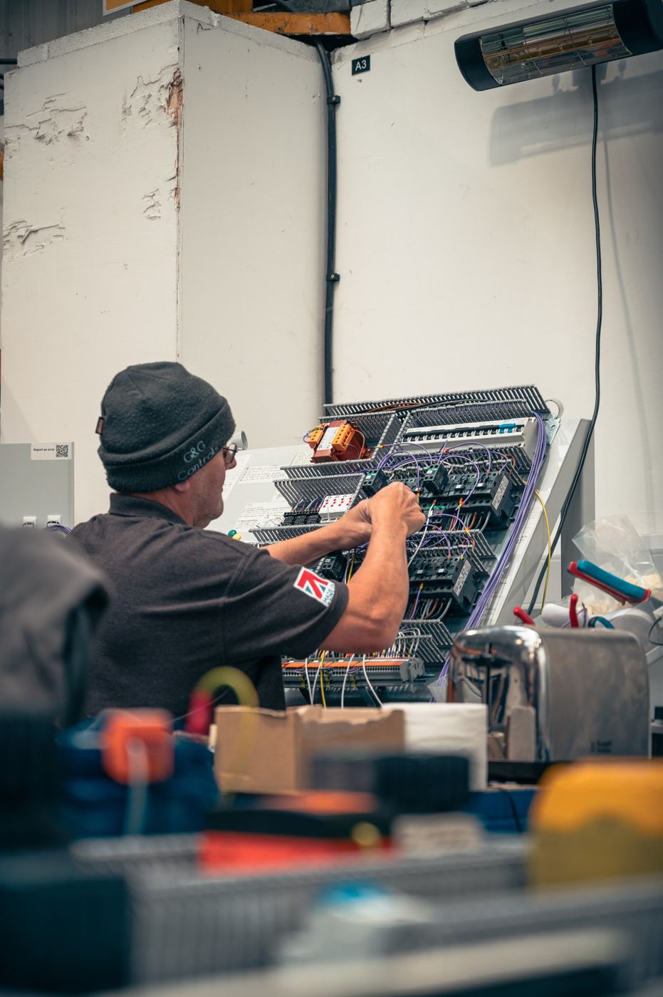
Star/Delta motor starting is a common method used to reduce the surge in current and torque during the starting of large motors. However, sometimes there can be errors when installing the starter and connecting the motor.
The main problem with starting a large 3-phase motor direct online (DOL: from nothing to 100% almost instantly) is the high inrush current, typically 6-8x the motor's full load current (FLC) rating. Star/Delta is one method to reduce the start-up inrush current.
Another major advantage of Star/Delta starting over DOL for pumps is to protect non-return valves (NRVs) and pipework from sudden pressure surges. When a motor starts DOL, the instant full speed operation can create water hammer causing excessive strain on pipework, NRVs and other equipment downstream of the pump. This can lead to premature wear, damaged seals, or valve failure. Star/Delta starting significantly reduces this damage by getting the pump up to full speed in two steps. The lower starting torque minimizes shock loading on NRVs, allowing for a smoother pressure build-up in the system, extending the lifespan of both the valves and the pipework.
Star/Delta starters are usually made up of three contactors (main, star, delta) with one thermal overload, either connected to the output from the main contactor or connected before the whole starter. Our preference is usually connected after the main contactor.
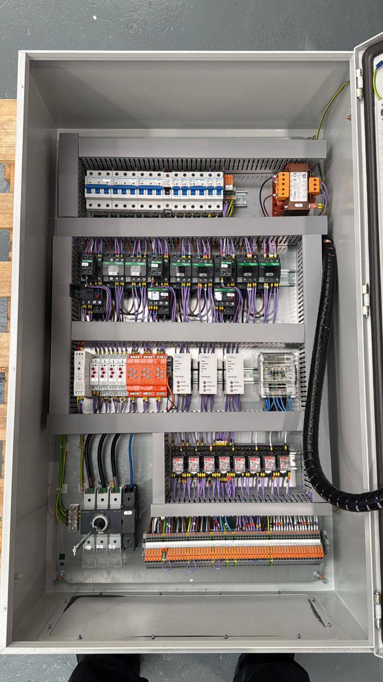
So, how does it work? The motor starts using the main and star contactors, which reduces the voltage applied to each winding to 58% of the line voltage. This results in a reduction of both the starting current and torque to 1/3 of their full load values. Then, once the timer has reached its set time (normally between 3-10 seconds, it should be set to the time by which the motor has reached 80-90% of its full speed) it'll switch from the star contactor to the delta contactor, where the motor is supplied with full line voltage and delivers full torque.
When the star contactor is energized, the three windings of the motor are connected together at a common point, forming a star configuration. This means each winding only receives a reduced phase voltage, lowering the initial inrush current. Once the timer triggers the transition, the star contactor disengages, and the delta contactor energizes. This reconfigures the motor windings so that each one is connected end-to-end with the next, forming a delta configuration. At this point, the motor receives full line voltage, allowing it to operate at full power and torque. The panel achieves this transition by using an automatic timer or control relay to switch between star and delta contactors at the correct moment, ensuring a smooth start-up process.
So, what's the confusion? Alright, let’s talk about the 58% we mentioned earlier. On a normal DOL motor starting you'd set your overload to the FLC of the pump. But here’s the thing - because the current is running through two contactors at 58%, the current 'seen' by the overload is lower. So to calculate the overload size you need to multiply the full load current by 0.58.
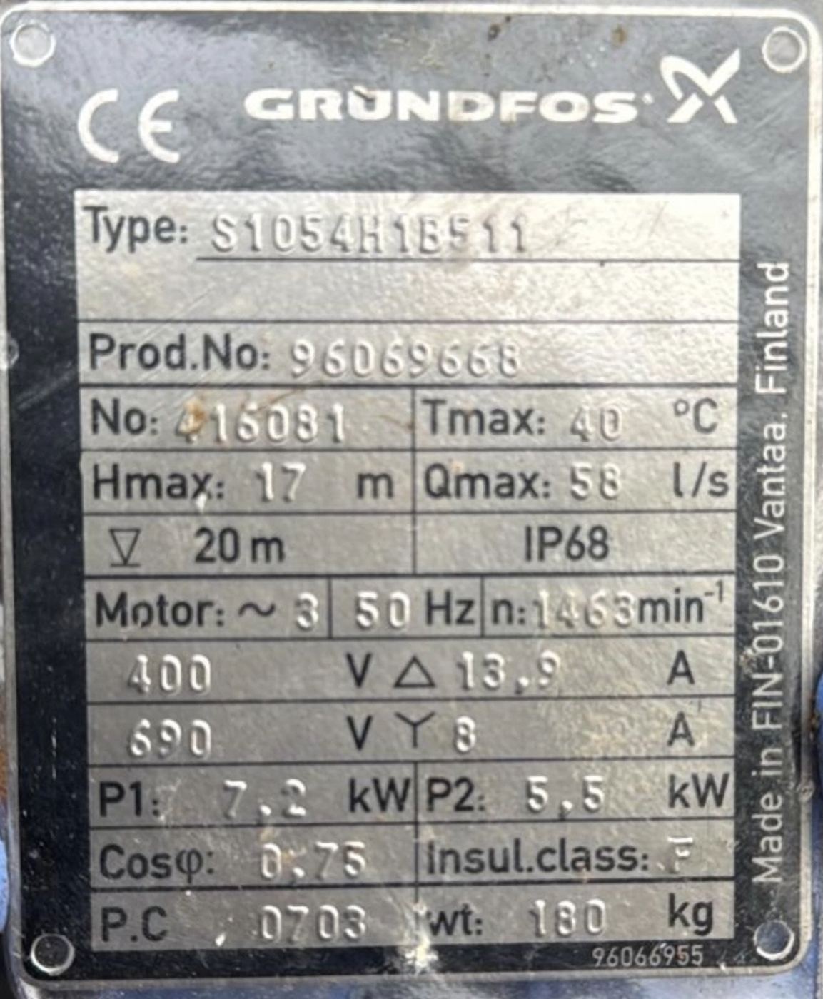
Here's an example - Let’s say you’ve got a 7.5 kW pump with a full load current of about 15A which is connected to a star/delta starter with the overload mounted after the main contactor. To calculate the overload size, you just multiply the full load current by 0.58.
15 × 0.58 = 8.7A
So, you’d set the overload to 8.7A, and you’re good to go!
To reduce customer confusion, we now fit these labels in every panel using star/delta motor starting!
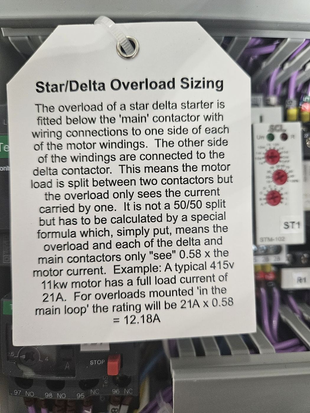
The information provided in this blog post is intended for general knowledge and guidance only. It does not constitute professional advice. Please consult a qualified professional for advice specific to your situation before making any decisions based on this information.
Written by the engineers at G&G Controls, a UK control panel manufacturer in Stoke-on-Trent. For general guidance only; consult a qualified professional for advice on your own installation.
Up next
Replacing failed inverters
Sometimes when the power to an inverter is turned off (power cut/maintenance/repair etc) the inverter won’t turn on again afterwards. What follows next is difficult explanations about why a perfectly working inverter has suddenly failed after the maintenance engineer worked on the equipment. Well he