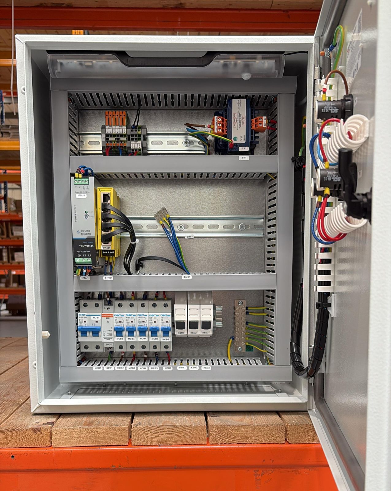
Why single phase motors need capacitors
By Tristan Newton, Commercial Director · 24 April 2026 · 4 min read
Let's start with a simple fact - three-phase motors are better than single-phase motors. More torque, no capacitors, fewer complications. But a huge proportion of real-world applications only have single-phase power available, and single-phase motors can't start on a live and neutral alone. That's where capacitors come in.
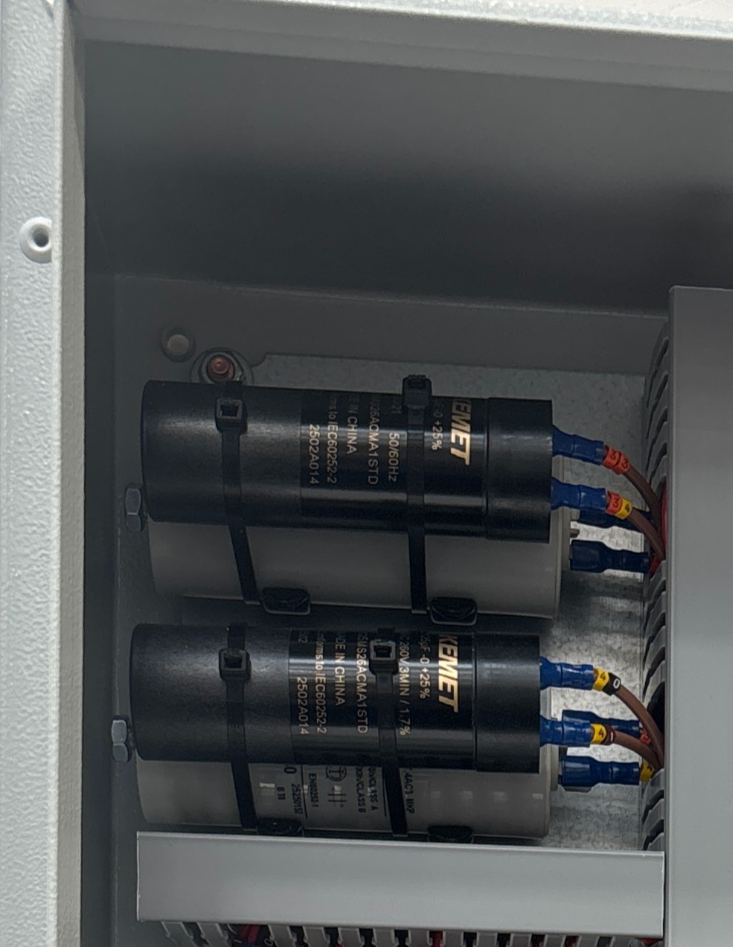
Capacitors effectively create a second phase to get the motor spinning. Many motors use both a start and a run capacitor - the start capacitor delivers a strong burst of energy to kick the motor into rotation, then drops out once it's up to speed, leaving the run capacitor to keep things smooth and efficient during normal operation.
How A Single-Phase Motor Actually Works
Picture a single-phase motor driving a pump. It runs on standard UK mains: 230V AC at 50Hz. The alternating current flips direction 100 times per second, creating a magnetic field in the stator - the stationary outer part of the motor. That field tries to spin the rotor (the inner rotating part), but here's the problem: with only a single phase, the force pulling the rotor clockwise and the force pulling it anticlockwise are exactly equal. The result? The rotor stalls or chatters in place without some external help to break the deadlock.
What a Capacitor Does
A start capacitor and start winding work together to create a second magnetic field that's slightly out of step with the main one. That phase difference means the combined magnetic pull rotates around the stator, giving the rotor a definite direction to spin in.
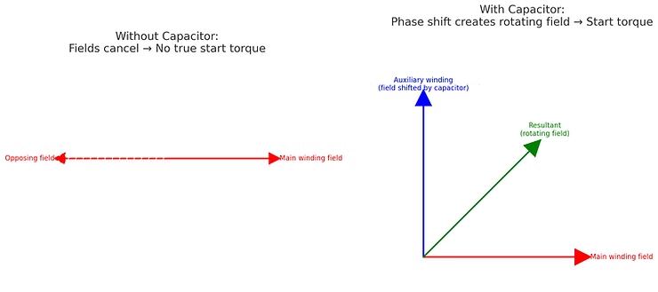
The start capacitor shifts the start winding's magnetic field by roughly 90 electrical degrees - simulating a second phase and generating strong starting torque, typically two to three times the motor's normal running torque. That burst lasts around half a second to two seconds. Once the rotor reaches about 70–80% of full speed, a centrifugal switch or external relay disconnects the start capacitor and start winding, since they've done their job.
The run capacitor is permanently connected. It contributes on start, but its real role kicks in once the start capacitor drops out - maintaining the phase shift between the two windings and keeping the rotating magnetic field stable. The practical result: the motor runs quieter, draws less current, and delivers steady power under load.
Capacitor Types
There are two common types: film and oil-filled.
For industrial applications, oil-filled is the standard choice. You'll recognise them by their larger cylindrical form factor. They're significantly more robust than film capacitors - more tolerant of temperature variation, better able to handle voltage fluctuations, and far less likely to degrade prematurely. Film capacitors, by contrast, deteriorate quickly under temperature swings or even modest voltage spikes, making them poorly suited to the kind of environments pump control panels typically operate in.
Voltage Rating
Every capacitor has a maximum voltage rating - the highest voltage it's designed to safely handle. This must always be higher than the voltage it will actually see in use.
In the UK, mains voltage sits just above 240V in practice, so a capacitor rated at 250V is the absolute minimum, and higher is better. A capacitor marked 220V is not suitable for a standard UK single-phase system - it's already operating near its limit before you've accounted for any fluctuation, and overvoltage is one of the fastest ways to kill a capacitor.
Capacitance: Getting the Value Right
Capacitance is measured in microfarads (µF) and is one of the most important values on the label. The required figure is set by the motor manufacturer and is specific to that motor - though as any engineer who's had to track one down will know, it's not always easy to find (see our separate post on Xylem Flygt capacitor sizes for a worked example).
Most capacitors carry a tolerance range, typically ±5% to ±20%, printed on the body. A motor specified for a 30 µF capacitor will generally run fine with one measuring 28.5 µF on a ±5% tolerance. Go outside that range, though, and you're asking for trouble - the wrong capacitance value can cause excessive heat, poor starting, and premature failure of either the capacitor or the motor itself.
Testing a Capacitor
Capacitors can be tested with most modern multimeters. A quick test can tell you whether a capacitor has failed outright or drifted significantly out of tolerance - both common causes of a single-phase motor refusing to start or running poorly.
This should only ever be carried out by a trained and competent electrician. A charged capacitor stores electrical energy and can deliver a serious and potentially fatal electric shock even when the power is off. Always discharge the capacitor before handling it.
- Isolate and de-energise the equipment fully. Lock off and prove dead.
- Discharge the capacitor - use a discharge resistor or an insulated screwdriver blade briefly across the terminals. Never short it with bare wire.
- Remove the capacitor from the circuit.
- Set your multimeter to capacitance mode - the symbol looks like two parallel lines (representing capacitor plates), often alongside the F symbol.
- Connect the probes to the capacitor terminals - polarity doesn't matter for AC capacitors.
- Read the value and compare it to the rated µF on the label. If it's outside the stated tolerance, replace it. If the meter reads zero, open-circuit, or wildly off, the capacitor has failed.
A failed capacitor is one of the most common and easiest-to-fix causes of a single-phase pump motor not starting - and a replacement is usually a few pounds. Always replace like-for-like on both µF value and voltage rating.
The information provided in this blog post is intended for general knowledge and guidance only. It does not constitute professional advice. Please consult a qualified professional for advice specific to your situation before making any decisions based on this information.
Written by the engineers at G&G Controls, a UK control panel manufacturer in Stoke-on-Trent. For general guidance only; consult a qualified professional for advice on your own installation.
Up next
How to run a 3 phase motor on a single phase supply
If you've ever faced a situation where you've got single-phase power but need to run a three-phase motor—say, a pump in a remote water treatment site—you've likely looked at single-phase-in, three-phase-out inverters.